This page is not compatible with Internet Explorer.
For security reasons, we recommend that you use an up-to-date browser, such as Microsoft Edge, Google Chrome, Safari, or Mozilla Firefox.

New Improvements Enabling Geometrical Compensation of AM Parts
Particularly with metal AM technologies such as L-PBF or EB-PBF, part distortion can occur caused by large temperature variations and long build times. The correction of such variations is tedious due to the large variety of influencing factors. With the established mesh compensation function, this can be solved and following iterations can be reduced dramatically. The mesh compensation function is part of the Manufacturing Geometry Correction Module for VGSTUDIO MAX or VGMETROLOGY and is based on optical or CT scan surface data. The latest release covers more advanced requirements and workflows including sintering compensation.
In the current state of additive manufacturing (AM), users have complex hardware and software process chains and are creating complex parts to achieve the full potential for their products. Particularly with metal technologies such as L-PBF and EB-PBF, many influential process parameters must be considered.
A typical problem is part distortion caused by the high energy input by the lasers or electron beam and the large temperature variation over time and over large build volumes. As a first step, the parts must be measured to detect such issues.
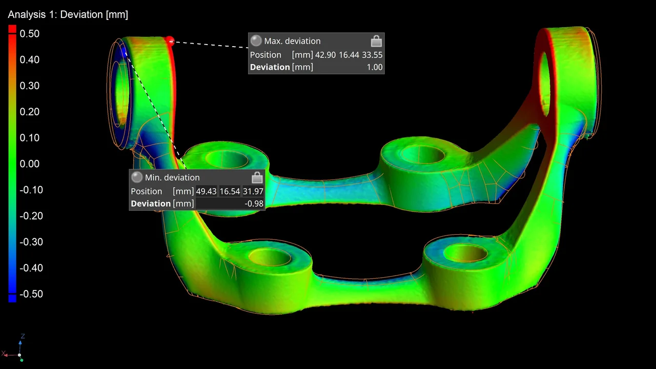
One common way is optical scanning, which is fast and sufficient in most cases. However, CT scanning is also a suitable tool for detecting and measuring part distortion. In both cases, a comparison of the measured geometry to the planned geometry is done and a significant distortion is measured.

Nominal-actual comparison of an additively manufactured bracket showing deviations >1mm in the upper sections
Using the measured results of the distortion, the user needs to find a way to eliminate that distortion and change the design or certain process parameters for the next build job. Usually, this is a tedious process over lots of iterations.
Our solution for that problem is the mesh compensation function:
As shown in the video, we need a planned geometry and measured surface data (usually optical or CT scan) for this workflow. Our goal is to create a surface mesh that compensates for the difference between the actual object and a reference object.
As a first step, both data sets must be registered, and control points must be created for the following compensation. The control points can be set automatically or manually defined.
The result is a mesh with the same quality and node structure as the polygonized nominal model. This works for single parts, build jobs with several identical parts, or differently designed parts.

Result of a mesh compensation: CT measured surface in gray, expected geometry in orange and compensated geometry in yellow
In the most recent version 3.5.2, we introduced the ability to add two different compensations with different scales in a single workflow. This is very valuable for sintering processes. The user can compensate the warpage and the shrinkage from sintering in one workflow.

Demonstration of different geometries for the mesh compensation for sintering processes
About Volume Graphics and Hexagon
Volume Graphics GmbH has been developing software for non-destructive testing based on industrial computed tomography (CT) for over 20 years. Customers around the world, e.g., from the automotive, aerospace, and electronics industries, use Volume Graphics software for quality assurance in product development and production. In addition to its headquarters in Heidelberg, the company has branches in the USA, Japan, Singapore, and China. Learn more at www.volumegraphics.com and follow us @volume_graphics.
Since 2020, Volume Graphics has been part of Hexagon. Hexagon is a global leader in sensor, software and autonomous solutions. We are putting data to work to boost efficiency, productivity, and quality across industrial, manufacturing, infrastructure, safety, and mobility applications. Our technologies are shaping urban and production ecosystems to become increasingly connected and autonomous – ensuring a scalable, sustainable future.
Hexagon (Nasdaq Stockholm: HEXA B) has approximately 21,000 employees in 50 countries and net sales of approximately 3.9bn EUR. Learn more at hexagon.com and follow us @HexagonAB.
